Shapeoko 3 – Overview and Build
First stating the obvious: this is a high level overview and build article. Carbide 3D did not send this machine to me for free like Inventables is doing to every person with a thousand YouTube subscribers so all thoughts and opinions presented here are solely my own and are not driven by getting more free “swag”. I did reach out to Inventables several months back in an attempt to get their machine however they never responded to my email. Ironically I received a Twitter follow from them the same day I sent it so someone *did* read it but couldn’t be bothered to respond.
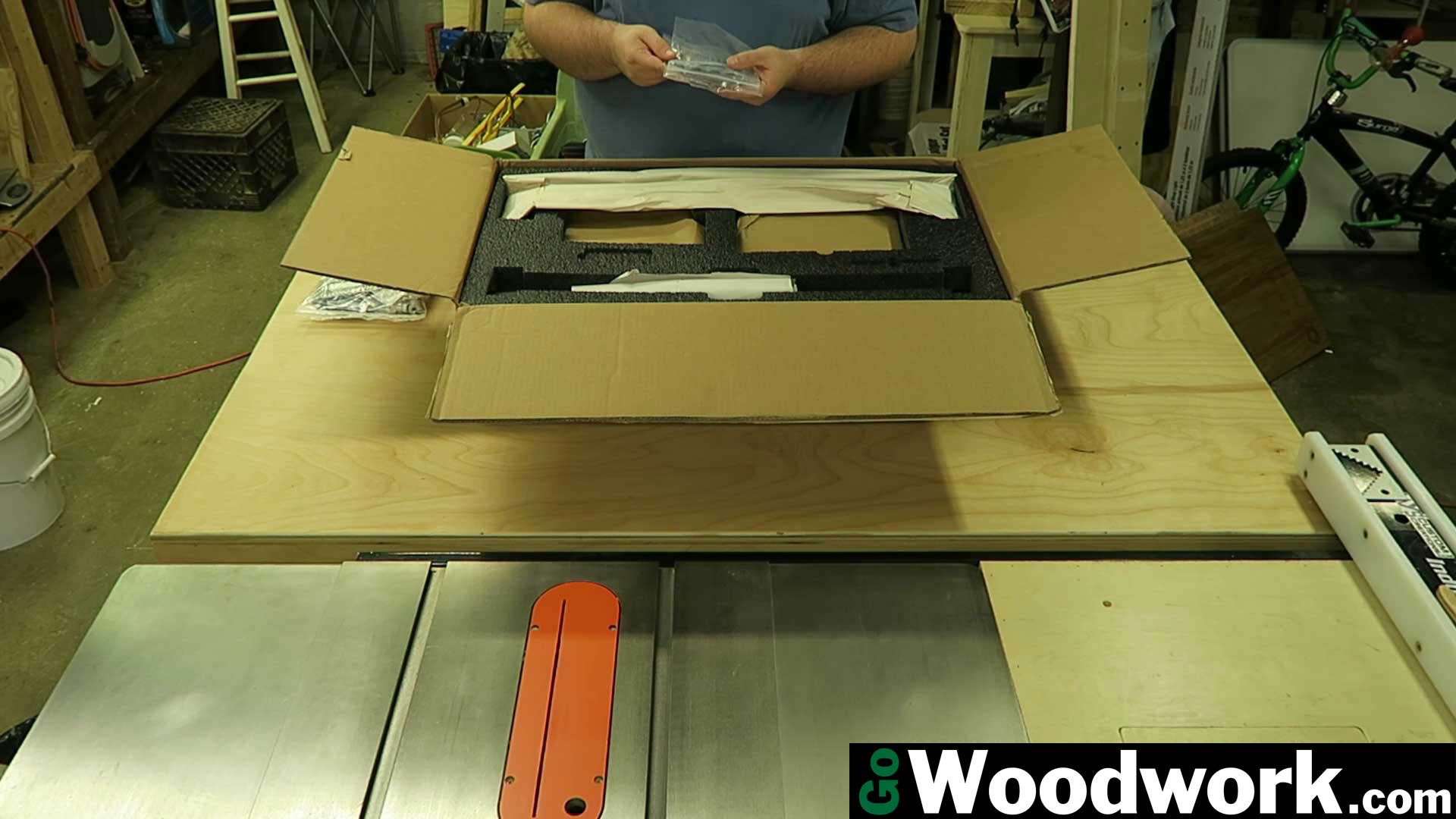
The Shapeoko 3 took about a month to ship after pre-order. It comes in a single box weighing about 55 pounds (25 kilograms) and is extremely well packed using molded foam. None of the powder coating was scratched and the aluminum extrusions were pristine. Great care has been taken by the engineers to ensure the package arrives undamaged.
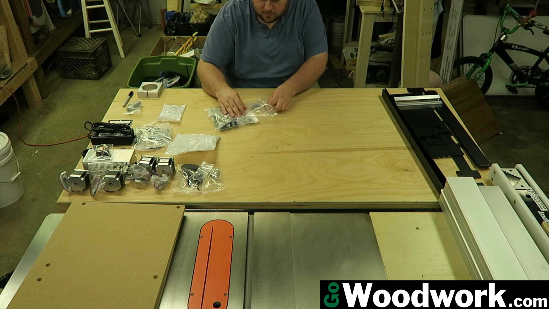
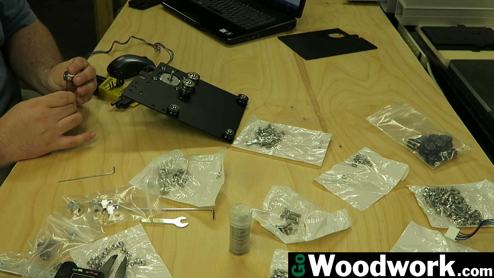
All of the hardware are provided in individual bags (most contain the same thread sizes). Fortunately, the two large quantity bolts, M5 x 16 and M5 x 20, were in their own bags since there is more than 25 of each. Smaller quantities (such as M3 and M6) were mixed together. Two cents worth of labeling for each bag would have saved a ton of time figuring out sizes. Of course, if I lived in a metric country and was more familiar with metric
sizes, this would probably be much easier. I talk in 1/4-20, not base-10 (and prefer to keep it that way).
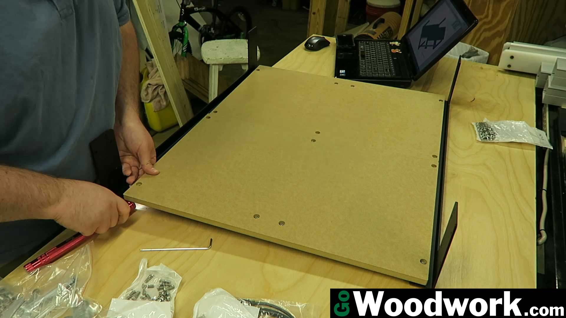
The waste board is provided in two halves consisting of 3/4″ MDF.
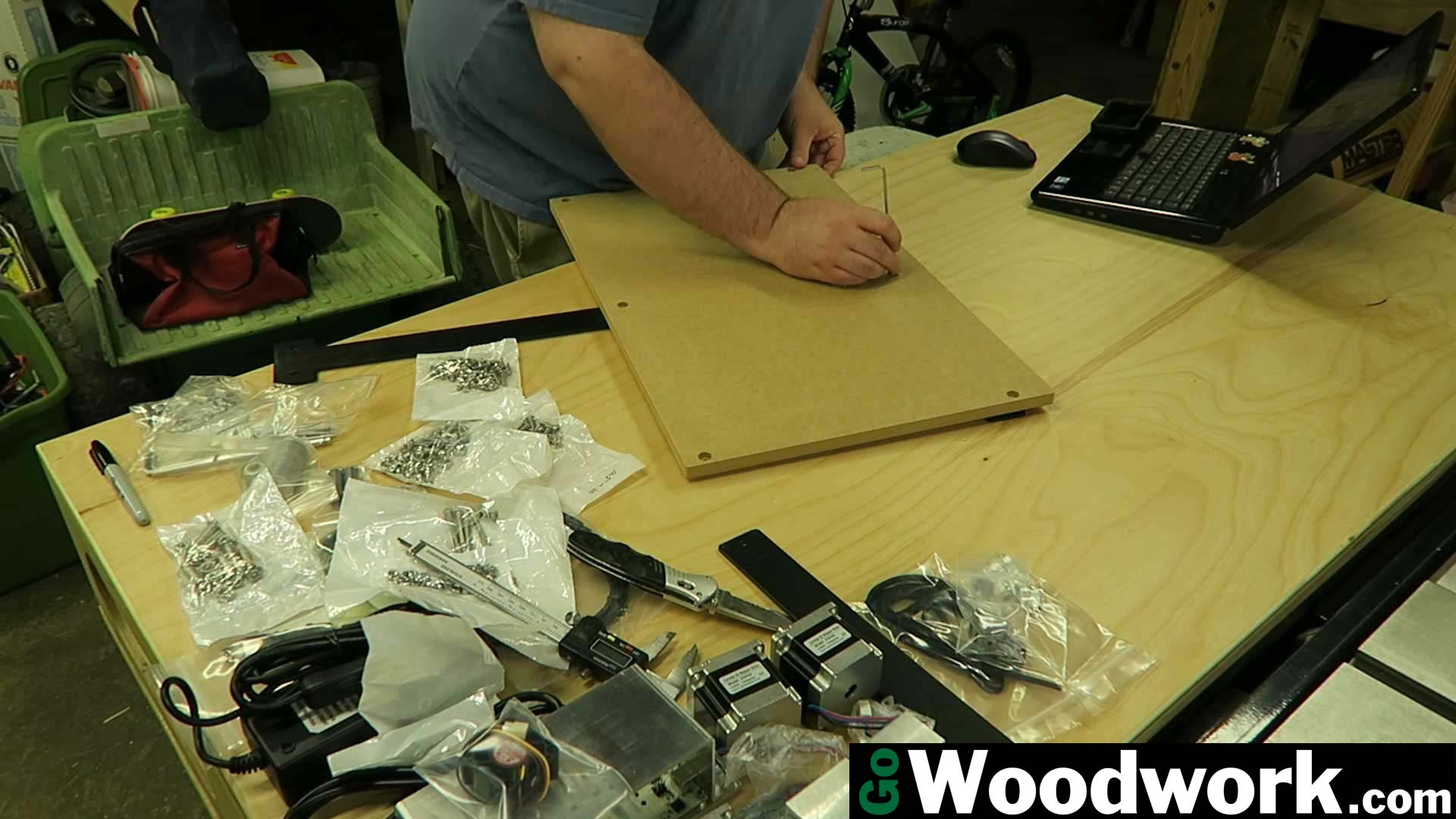
I was a bit disappointed at the fit and finish of this step. It seemed to be harder than it should have been. I later found using a flash light to illuminate the surface below really helped get everything lined up.
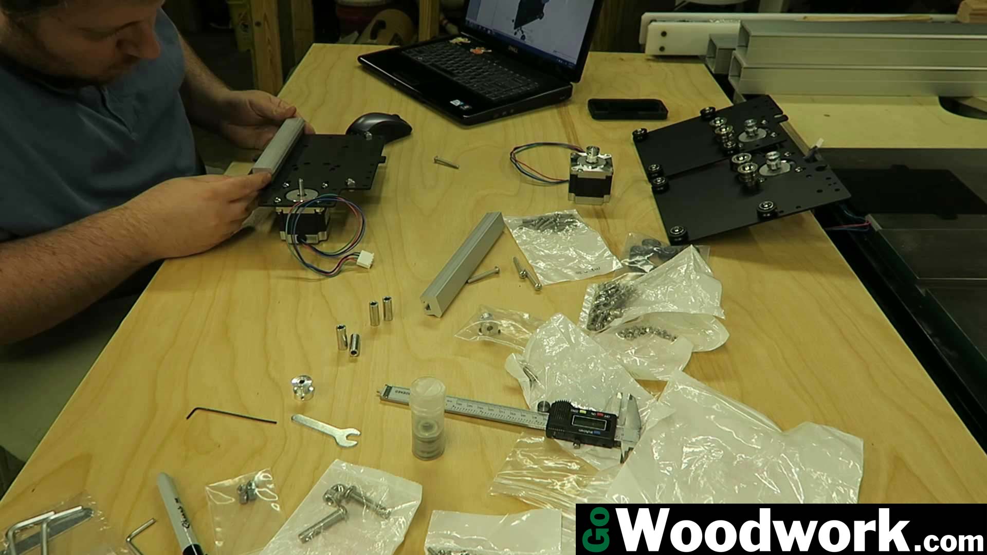
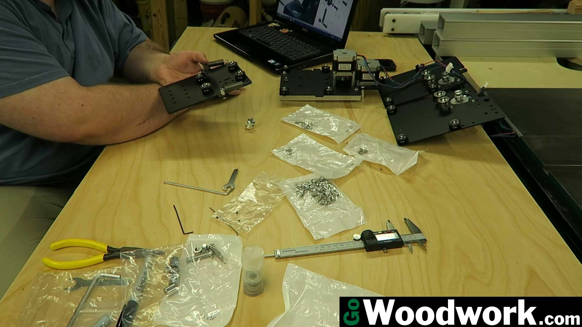
The two Y axis assemblies are straight forward and the instructions cover it very well. The second plate is assembled in a mirror image of the first.

The included toolkit (while adequate for most parts of assembly) does have deficiency. I found was the 1.5mm hex wrench to be over-sized (possibly due to the zinc plating) by at least 0.04mm (measured 1.54mm) I ended up using my own forged hex keys (measured 1.48mm). The included wrench simply could not fit into the set screw for the GT2 pulleys without blowing out the threads or getting stuck. I’ve noticed in other build videos that a quality pair of Stanley pliers were included however it appears that the cost was saved by including an incredibly cheap set of wrenches (most likely made in China). Another fiddly operation is attempting to tighten the nuts for each stepper motor. Due to the size and space constraints on the motor, getting a wrench on the nuts is difficult without slipping.
Overall, the toolkit quality is well, for lack of a better term, poor.
The X and Z axis proved to be more difficult. While the instructions are certainly lacking, assembly is still able to be figured out.
Use a caliper to ensure the two Z axis rails are parallel and square. I found that spreading the rails to the maximum width was required due to the v-wheels not spreading wide enough despite positioning the eccentric nuts in their outward most position.
Prepare to bang your head against the wall at least once while figuring out the X and Z axis assembles. You will have to navigate between about 6 pages of drawings to figure everything out. Of course, these are spread throughout the assembly instruction PDF so take a breather if you become frustrated with this.
Another fiddly part is the way the springs mount onto the carriage. They sandwich between a bolt head and an aluminum spacer forcing you to bend a tighter radius onto the spring. This could be solved (and was) by adding a #10 washer to each spring hold thus saving you from being forced to deform the springs.
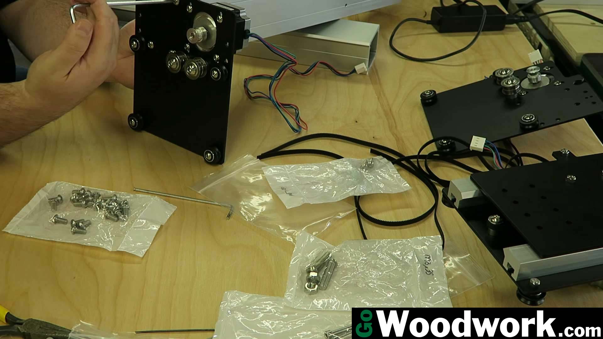
If the X and Z assemblies frustrated you then take a chill pill. The instructions are absolutely HORRIBLE in demonstrating how the belt should be attached and marry the two axis together. It took about an hour of reading several articles, looking at numerous photos, forum posts, and videos to figure out exactly what needs done. If you can figure this part out without jumping off a bridge then congratulations, you’ve just about got the project licked but if not:
- Place the closed loop belt over the lower stationary pulley
- Loop around the stationary GT2 pulley
- Slide the belt between the idler pulleys so they make a triangle formation
- Keep tension on the belt while sliding the entire Z axis carriage onto the X axis carriage
- Loop the belt over the upper stepper motor

This is where Carbide 3D really begins to shine in their engineering process. There are no ridiculous taps or tapping screws to bother with. I don’t know why Inventables is still resorting to such an unfinished product. Surely it would take no more than 5 minutes per machine and a quick jig to tap each hole. Good luck if you need to remove those X-carve rails later on, you’ll probably end up having to cut larger threads each time you do.
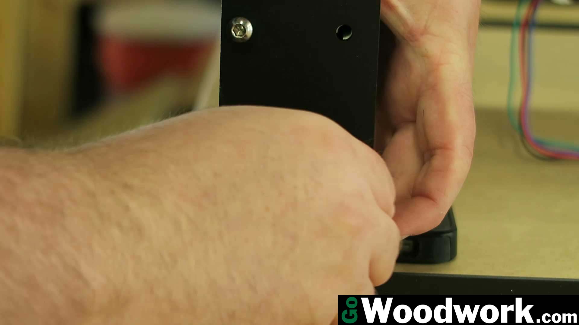
The Y axis rails install just as beautifully as they look. Shim one end of the rail to an approximate height so that inserting the hardware is much easier. When all four sides were attached, it was approximately 0.5mm off in height which is very impressive to me.
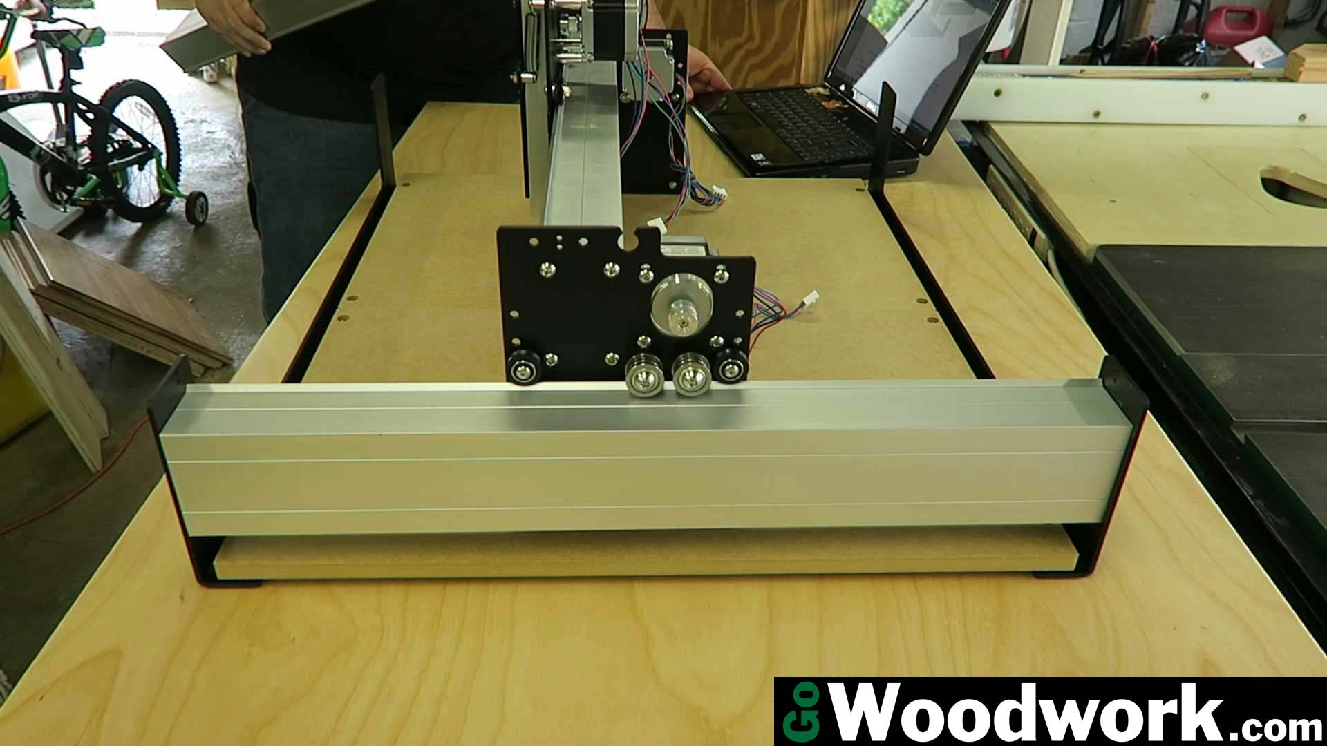
The instructions really provide no written instruction or diagrams on how the belts are to be installed. All three of the axis belts are the same length so feeding them between the idler bearings and over the GT2 pulley does make sense. Small bits like this missing from the assembly instructions is what take the machine from “Great” down to “Average”.
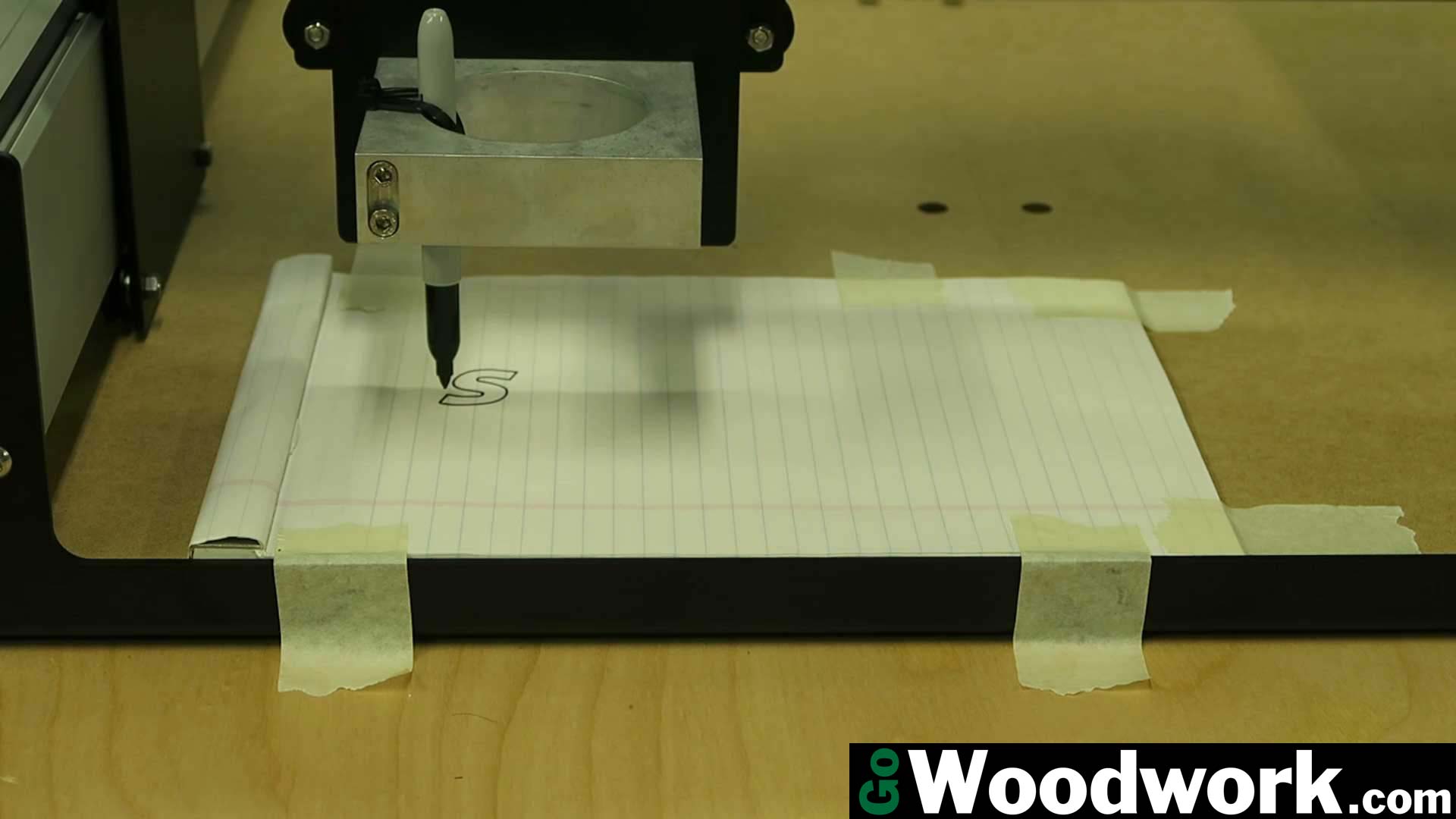
Proper tension is required to ensure the motors do not slip during operation. Just because the “Hello World” with a marker performs flawlessly doesn’t mean that it is properly tensioned. Addition of the trim router really adds to the amount of torque applied to the machine so without proper tension you will have poor results.


Besides the rails being pre-tapped there’s one area where there is no competition between the Shapeoko 3 and the previous/competitor models. No more terminal strips, drag chains, or worrying about flipping the stepper motor wires. All of the motors have modular connectors and the board is labeled with the proper axis.
The only other part of the entire build is a small laptop-style power supply that has a convenient in-line power switch. Communications are ran through USB like other machines so there’s no huge power supply to store or build a case for. I also love there’s no fiddly Arduino and G-shield to vibrate apart or become shorted. The electronics look like they were engineered with simplicity in mind. There’s nothing not to love about this.

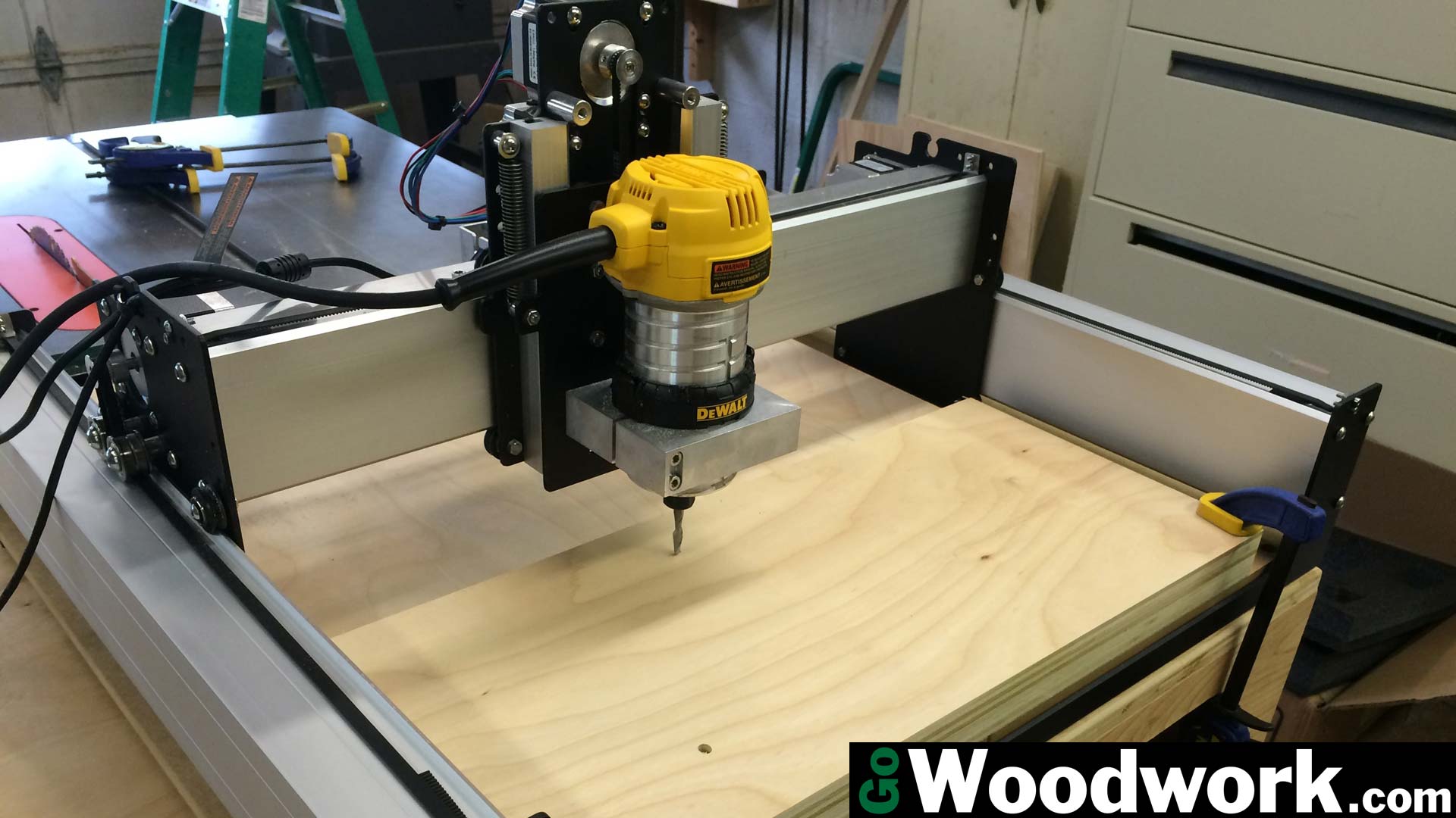
The Shapeoko 3 ships with a mounting bracket for the Dewalt DWP611 trim router and I’m glad they chose it over others. With the lighted base and variable speed, it’s such a great addition to the machine.
I hope you enjoyed reading and seeing the photos as much as I did assembling the machine. While there were a few hitches along the way, overall the build went very smoothly. If you decide to take the plunge, feel free to email me about any issues you may have and I’ll do my best to help you out.